Structured illumination
Structured illumination applied to fluorescence microscopy is a super resolution technique which allows optical sectioning and improvement in both lateral and axial resolution.
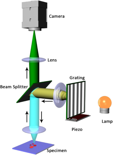
The principle, made simple:
- a periodic grid is projected onto the sample and swifted along one or more axis for a certain number of “steps” (phases);
- images are recorded at each step of each angle;
- an algorithm processes the images and reconstructs the optical section;
- Illumination can be both from laser sources, LEDs or alogen bulbs;
- The grid can be generated by a Ronchi grating, a spatial light modulator or it can be obtained by merging two laser beams;
- The system needs a device which can synchronize the grid movement and image recording.
- The chance of using a common inchoerent light source, a DLSR/camera, a Ronchi grating moved by Arduino and a relatively easy image processing, makes the system way easier to build than a confocal;
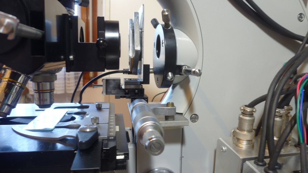
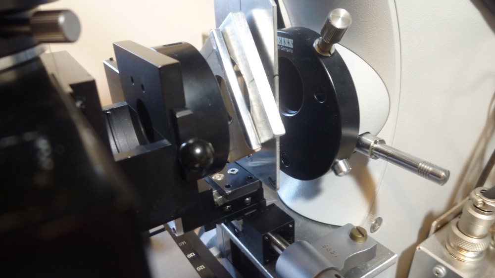
- The Zeiss Universal microscope has enough room between the epi-condenser and the fluorescence head to allow the placement of a Ronchi grating and all the parts (dovetails, motors) needed to rotate and shift it;
- My project wants to show that it’s possible to turn a 40 years old system into a relatively cheap, modern-like, fluorescence microscope with improved resolution and optical sectioning features.
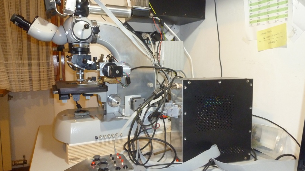
Zeiss Universal SIM: the prototype
Before starting to project the real parts of the rotating/swifting device I wanted to test if the principle could effectively work on my system.
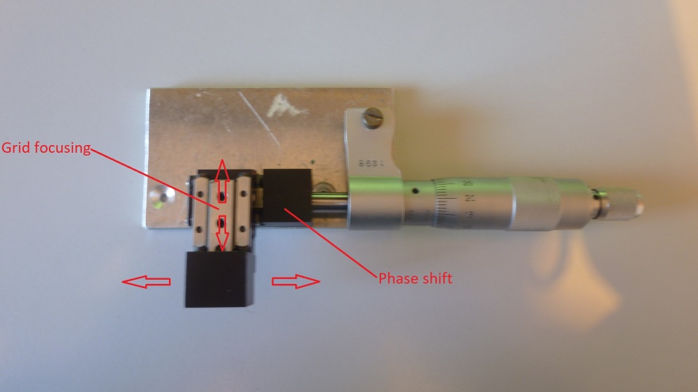
I could easily build a prototype with some spare parts I had from a broken hydraulic micromanipulator, a filter holder, a micrometer and some aluminium parts.
The device allowed me to manually focus the grating on the back focal plane of the objective, making it visible on the in-focus parts of the specimen and also rotate and swift the grating through the micrometer.
After some tests I could find the correct phase shift width. Three images are the minimum required for an optical section. More images and more angles, with more complex algorithms allow higher resolution and less artifacts, but slower data aquisition (very dependent on the sensitivity of the camera).

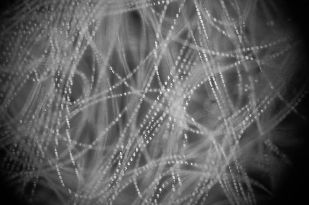
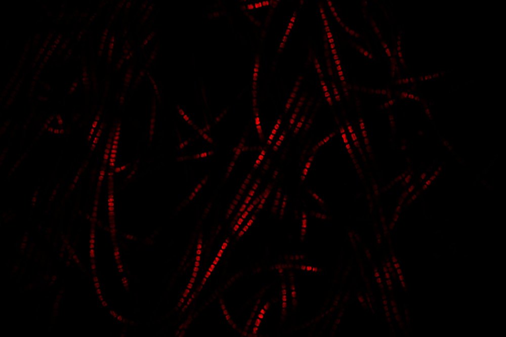
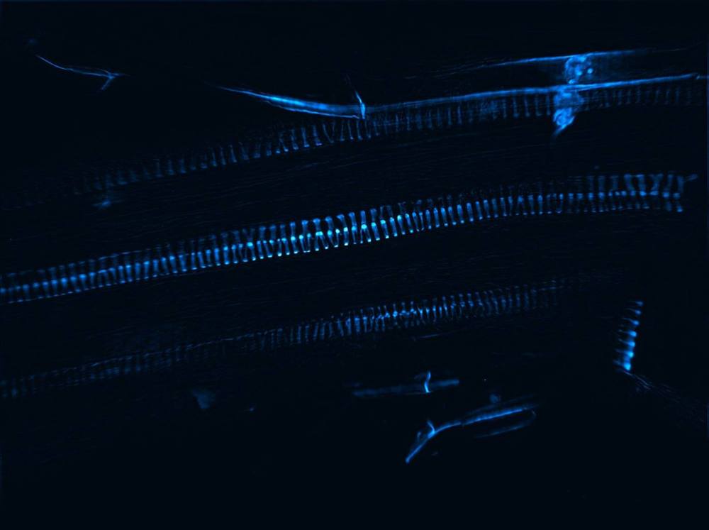
First images recorded with my Canon 600D with the superimposed grid:


Zeiss Universal SIM: the project
The system includes some newly built parts and some modified original parts:
- Light source
- Image recording device
- Mechanical device for grid control
- Arduino controller
Light source
One of the main issues about structured illumination is the relatively slow data aquisition speed (3 up to 15 images need to be recorded for each optical section).
In some commercial or sperimental systems this is fixed by using high power laser sources, SLM (spatial light modulators) or DMD and extremely sensitive cameras.
All those are expensive and out of an enthusiast’s budget.
The issue can be partially solved by the use of a powerful light source which, on the other hand will also increase photodamage.
For my needs, 365nm UV light will be my main excitation source.
The prototype I took my first images with used a 6w, double diode UV LED, which allowed to shot pictures with a 6-8 seconds exposure and 800 iso off my Canon 600D.


Being a two diodes LED wasn’t an issue when using the UV excitation filter UG1. The light was homogeneous on the sample.
The LED replaced the original halogen lamp in the Zeiss Universal lamphouse.
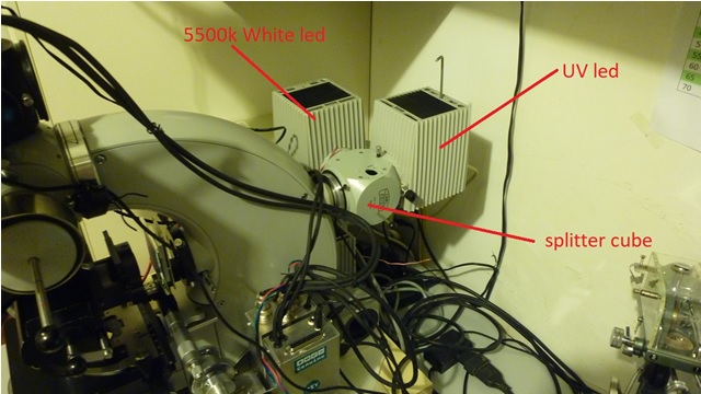
The splitting cube is a modified splitter cube for double view microscopes which is way cheaper (around 50€) and easier to find than the original splitting mirror cube (200€+).
It was easy to turn it into a double illuminator splitter since its dovetails are the same of the illuminators and it already contains a cube beamsplitter which, once heated in the oven, provides two perfectly fitting prisms.
Once glued onto a metal slider, the prism allows a manual, fast selection of the light source.


The prism has been glued to the metal slider. A black paper sheet blocks the light from the UV lamphouse (1) when the prism is in the white led (2) position.


At a later time I’ve also tried a 4 diodes, 10w UV Cree led with very good results. The exposure time dropped to 1-2 seconds and iso to 400.
The led needs to be placed closer to the illuminator position in the measure of about 5mm from the original position so that the lens can collect all the light from the four diodes.
It also requires some heavier heat dissipation.
After looking for a better UV led source, I came up with the final solution:
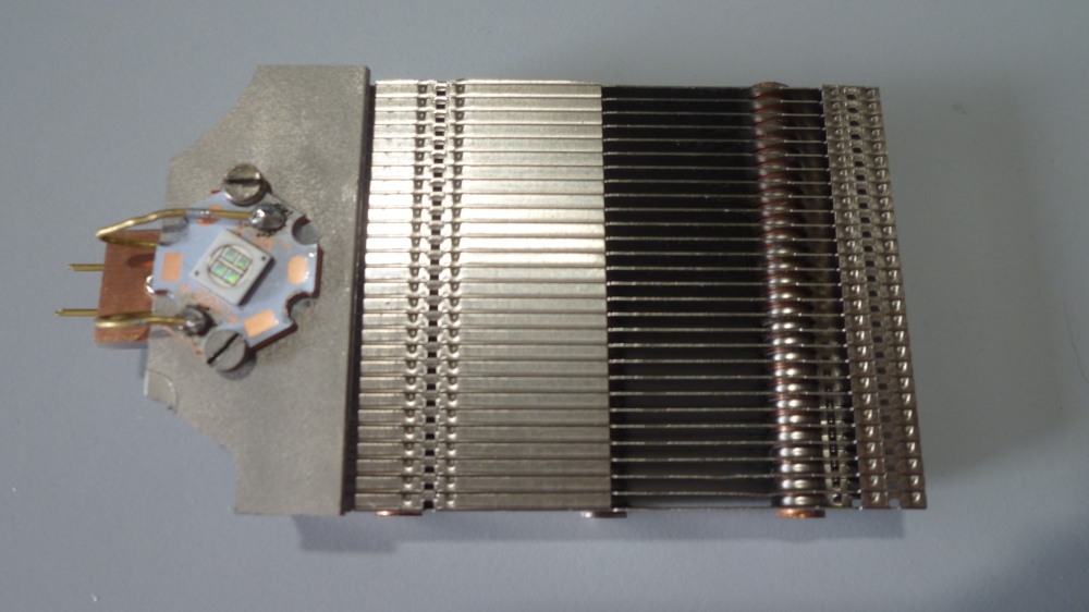
a Nichia NVSU333A U365 which with its luminous Intensity of 3640 mW is the most powerful UV led on the market, with small dimensions (6.8*6.8*1.9 mm).


The Nichia led was mounted on an old graphic card heatsink and inserted into the Zeiss illuminator. The top and bottom of the illuminator now has an aluminium cover to avoid UV light coming out.
The heatsink revealed to be overestimated
since the led is being run way under its maximum power. The UV output must be of better quality than cree leds.
The UG1 filter is not needed when using this led.
Recording device


As a recording device, a Basler GigE Scout scA1400-17gm monochrome camera was chosen.
Since the reconstruction algorithms work on grey scales, there was no need for a color camera. Also a higher sensitivity camera is always the best choice, for lower exposure times, being image recording the slowest part of the process.
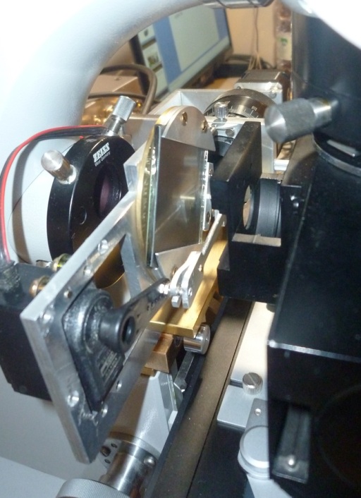
Mechanical grid control device
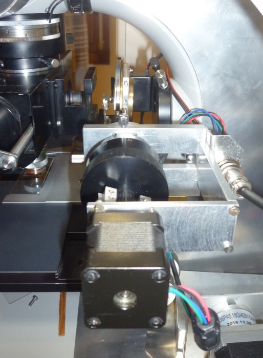
A mechanical device for controlling the grid movement was projected and machined.
The resulting movements are:
- Grid rotation through servo motor;
- Grid sliding through 200 step/rev Nema 17 motor;
- Grid focusing through manual sliding or gears system.
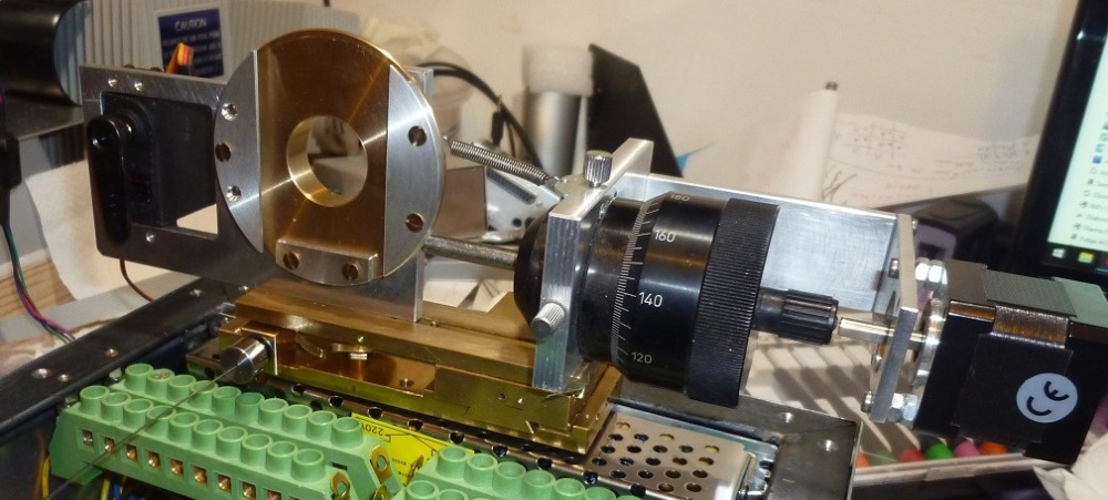
The device is screwed onto the focusing block of the Zeiss Universal, replacing the original upper lid.
Arduino control box
Moving the Ronchi ruling and synchronizing frame acquisition required the development of a dedicated control box.
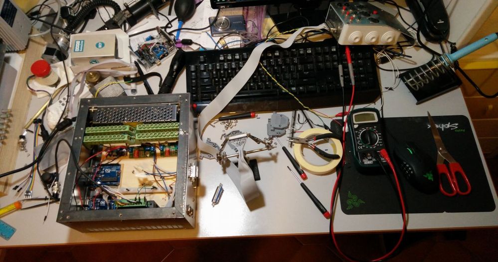
Two Arduino UNO rev3, two HALJIA TB6600 stepper motor controllers, a 2,8’’ Adafruit TFT monitor and a few step-down modules are being used to control the following parts:
- Motorized stage steppers;
- Focus stepper;
- Grid sliding stepper;
- Grid tilting servo;
- Camera acquisition trigger.
From the touch screen it is possible to select the recording mode: normal brightfield stack or SIM reconstruction.
When stacking is required, parameters like camera exposure time, depth of focus and number of frames required can be set.


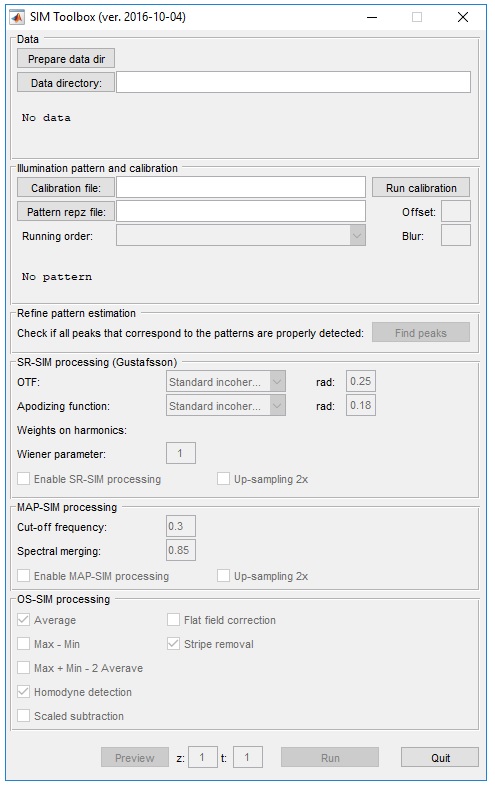
Image reconstruction
The freeware SIMtoolbox software is used to process the 15 (3 angles, 5 grid positions) frames that have been recorded for each slice. A 3D reconstruction is possible when multiple slices at different focus planes have been recorded.
Images can then be re-coloured using Imagej.
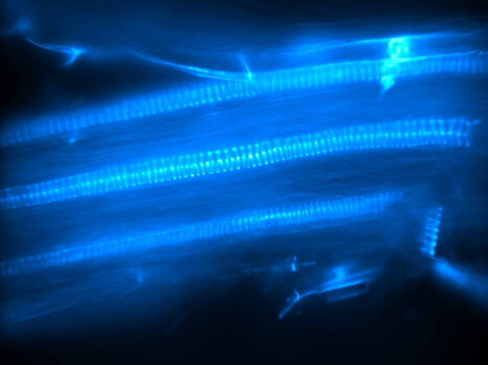
When target details emit fluorescence of more than one color, recording a slice for each colour is required by using a band-pass filter for each wavelenght.
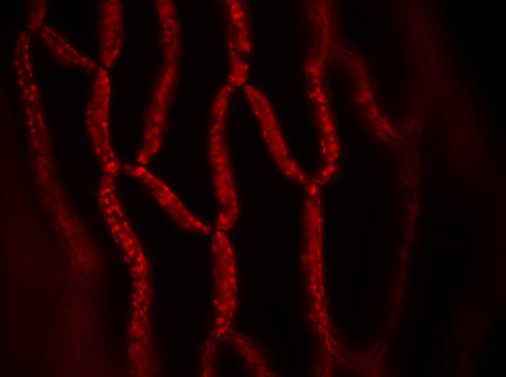
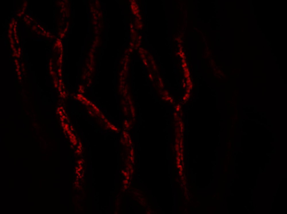
The first results on Sphagnum moss leaves are promising.
You can find a video of the scanning process here:
https://www.youtube.com/watch?v=ViBGOUhJGXg
Future improvements
Despite the initial good results, the system still has some improving potential. Many factors contribute to the final result and will need to be considered in the future:
- Grid density;
- Type of objective;
- Light source and collimation;
- Sample preparation;
- Recording device. The actual recording time ranges between 10 up to 15 seconds for one slice (15 images). A more sensitive device would considerably reduce this;
- Grid orientation/sliding range;
- Reconstruction parameters on SIMtoolbox.
References
[1] Micron Oxford, Advanced bioimaging unit http://www.micron.ox.ac.uk/research/super_resolution_microscopy.php
[2] Basler Scout cameras https://www.baslerweb.com/en/products/cameras/area-scan-cameras/scout/sca1400-17gm/
[3] Arduino https://www.arduino.cc/
[4] SIMtoolbox http://mmtg.fel.cvut.cz/simtoolbox/
[5] Adafruit https://www.adafruit.com/
[6] Zeiss Apotome https://www.zeiss.com/microscopy/int/products/imaging-systems/apotome-2-for-biology.html – http://zeiss-campus.magnet.fsu.edu/articles/superresolution/supersim.html
[7] Nichia http://www.nichia.co.jp/jp/about_nichia/index.html
[8] Structured illumination microscopy, Manish Saxena, Gangadhar Eluru, and Sai Siva Gorthi. https://www.osapublishing.org/aop/abstract.cfm?URI=aop-7-2-241
